How to use the Solar Flare Alert - Workshop Version
What you have in your kit:
A table tennis ball

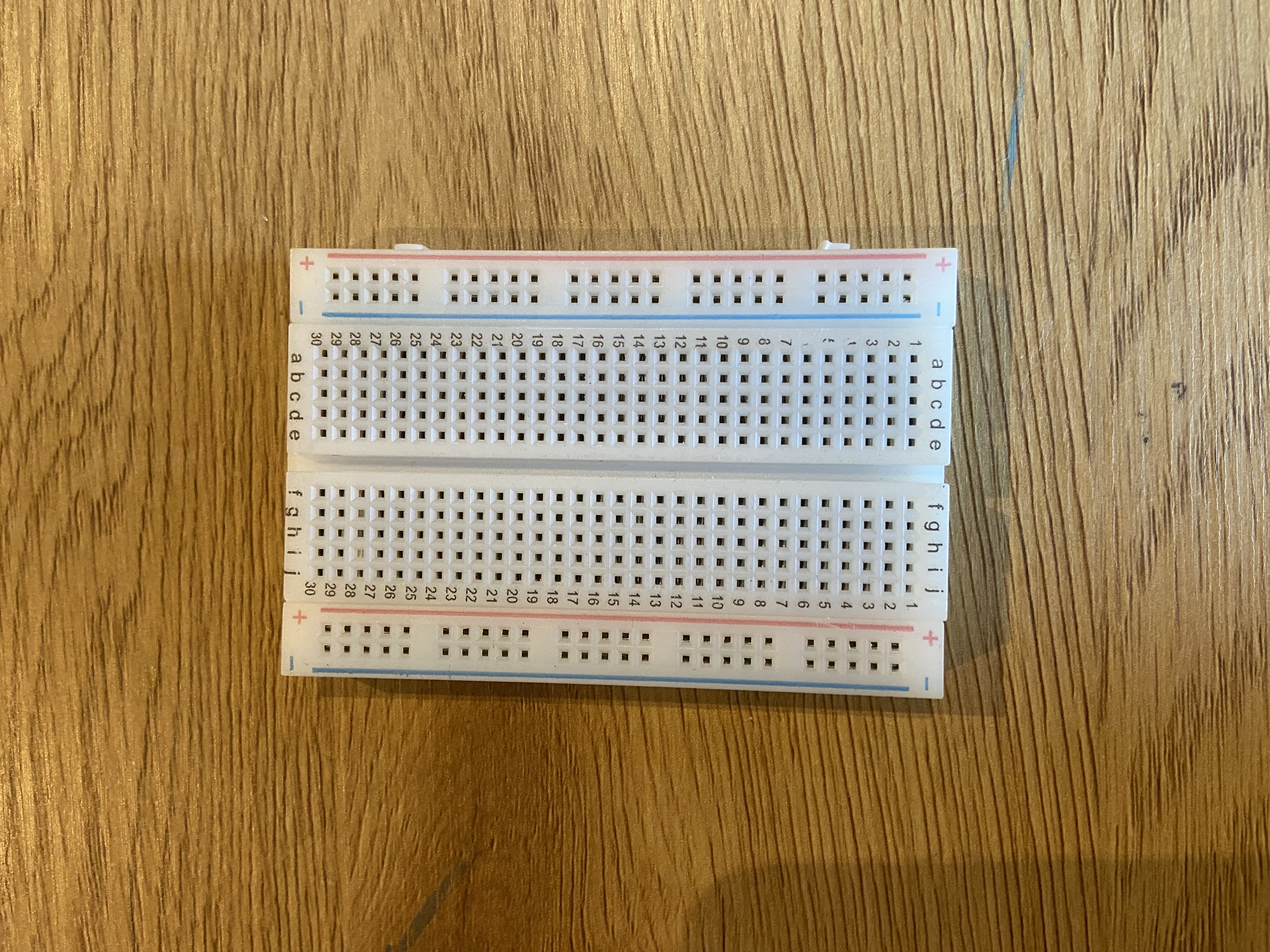
One white breadboard
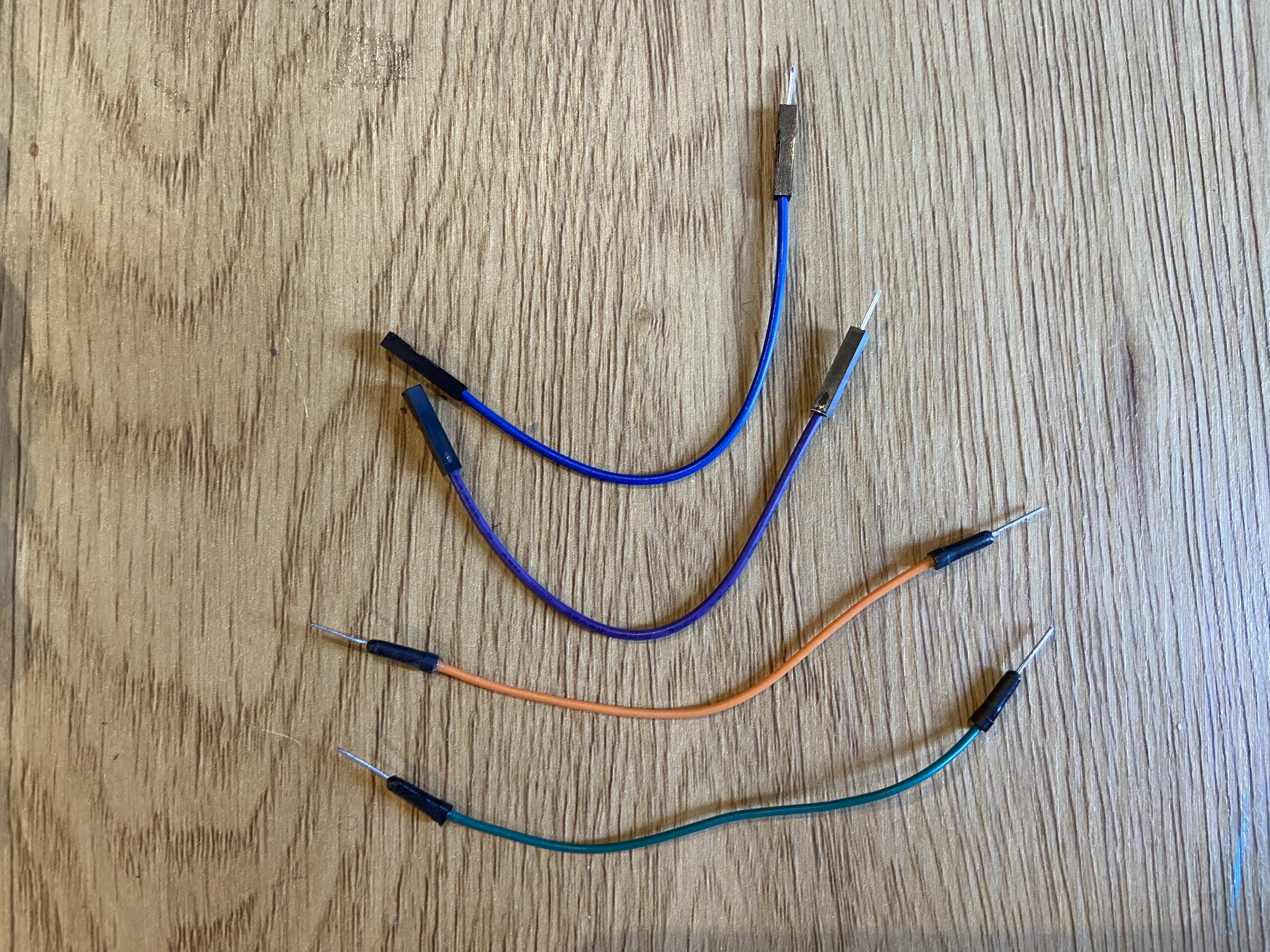
Wires
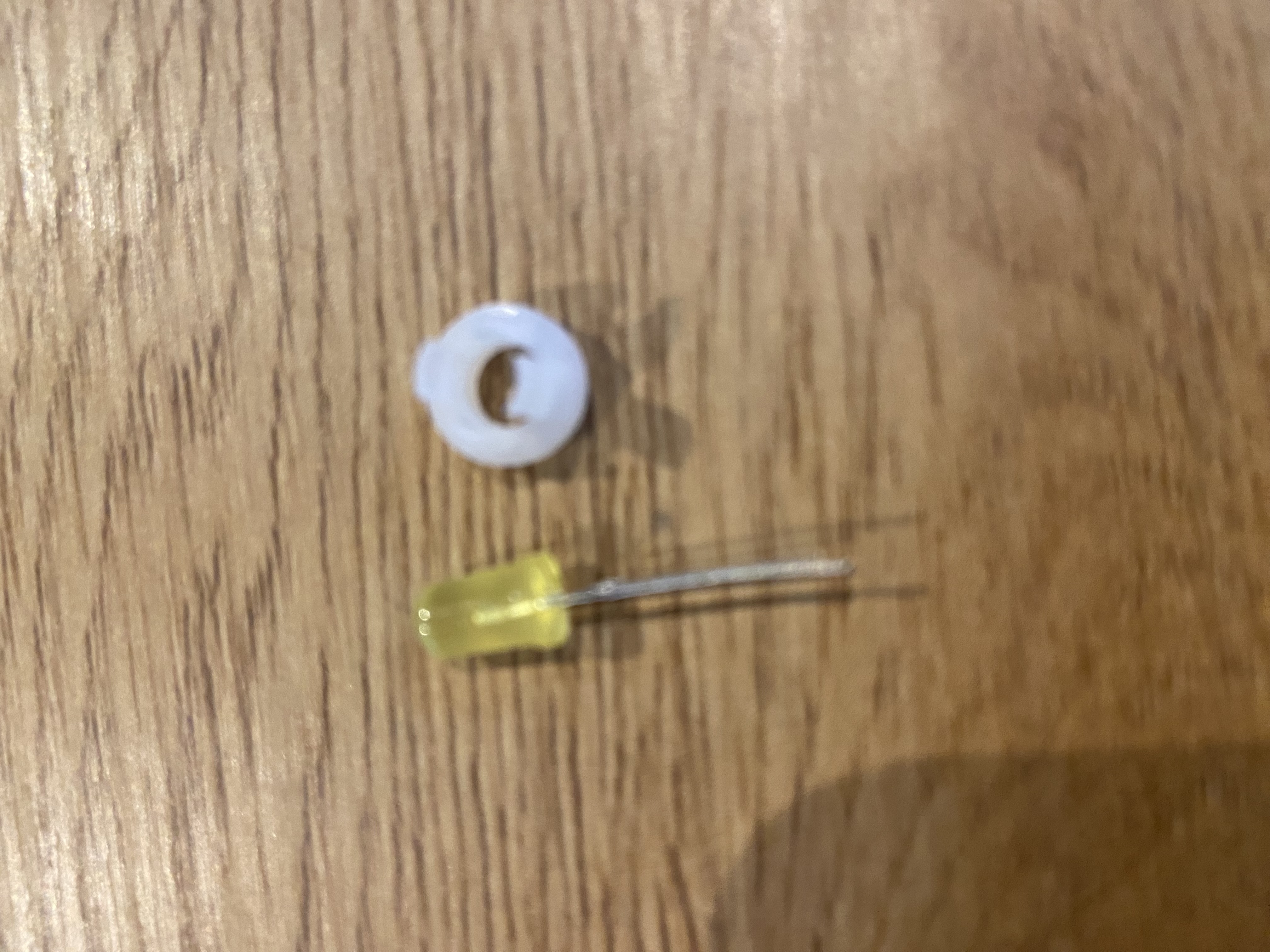
One LED with an LED holder
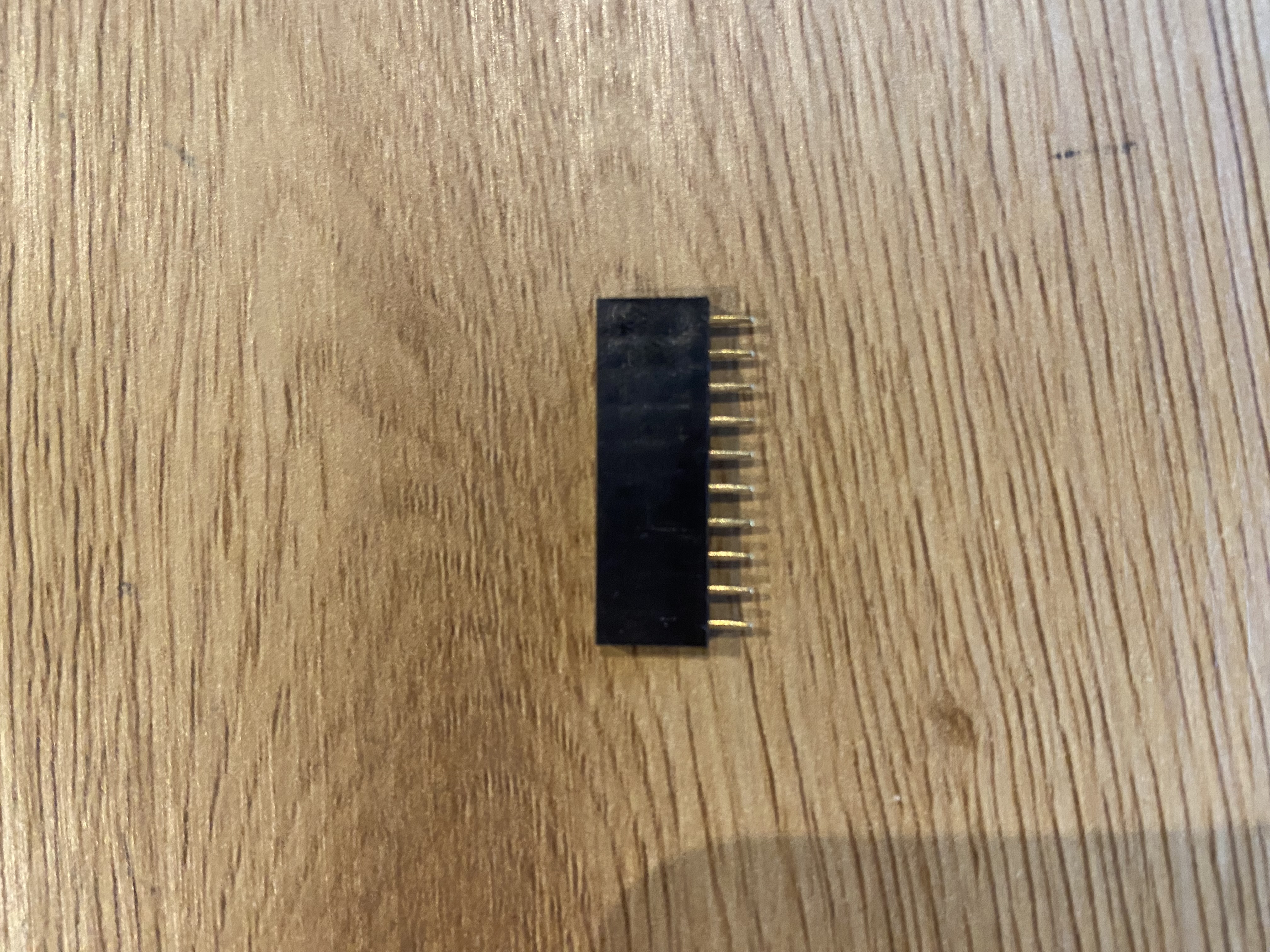
One wire holder
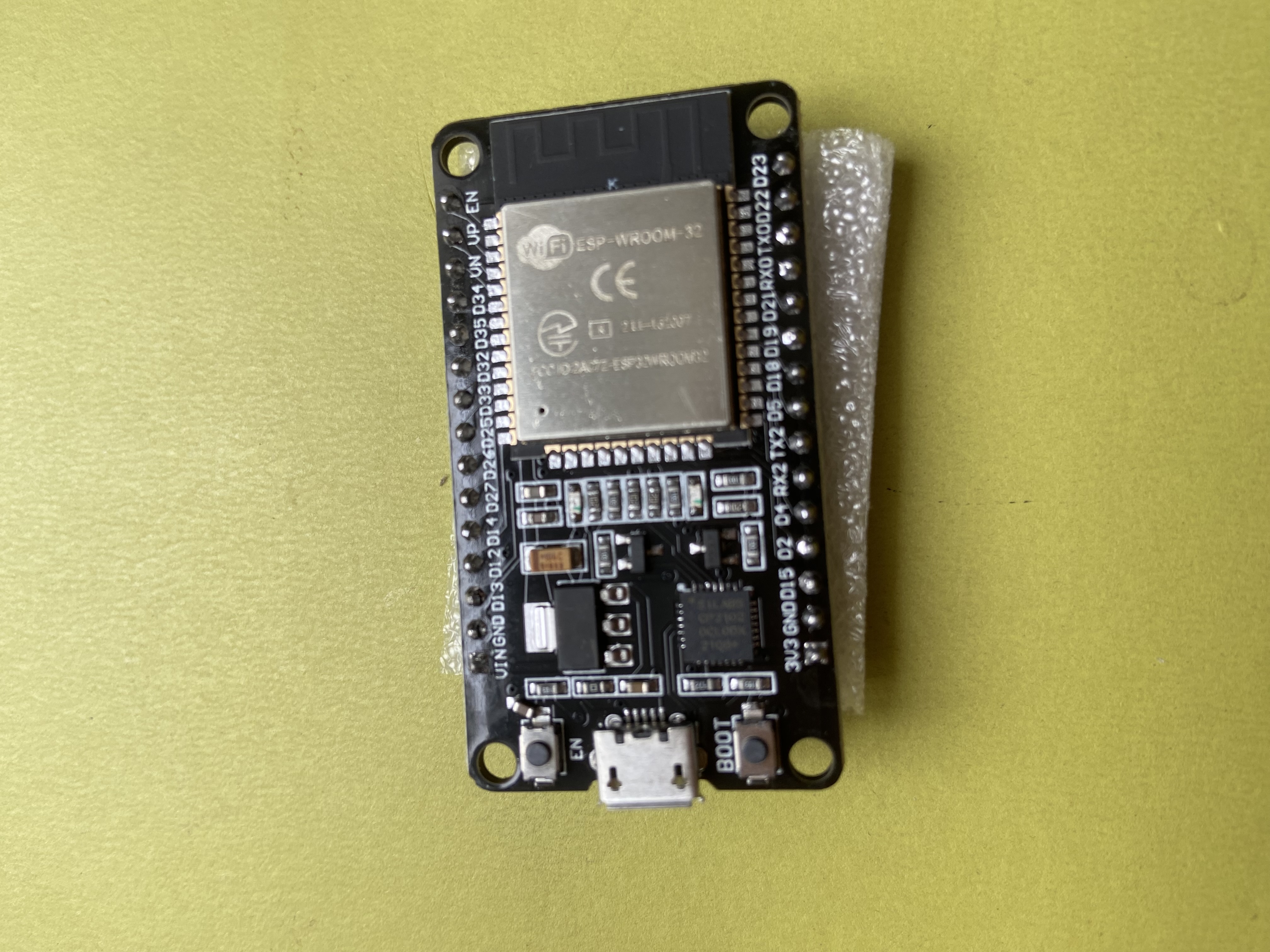
One ESP32 development board
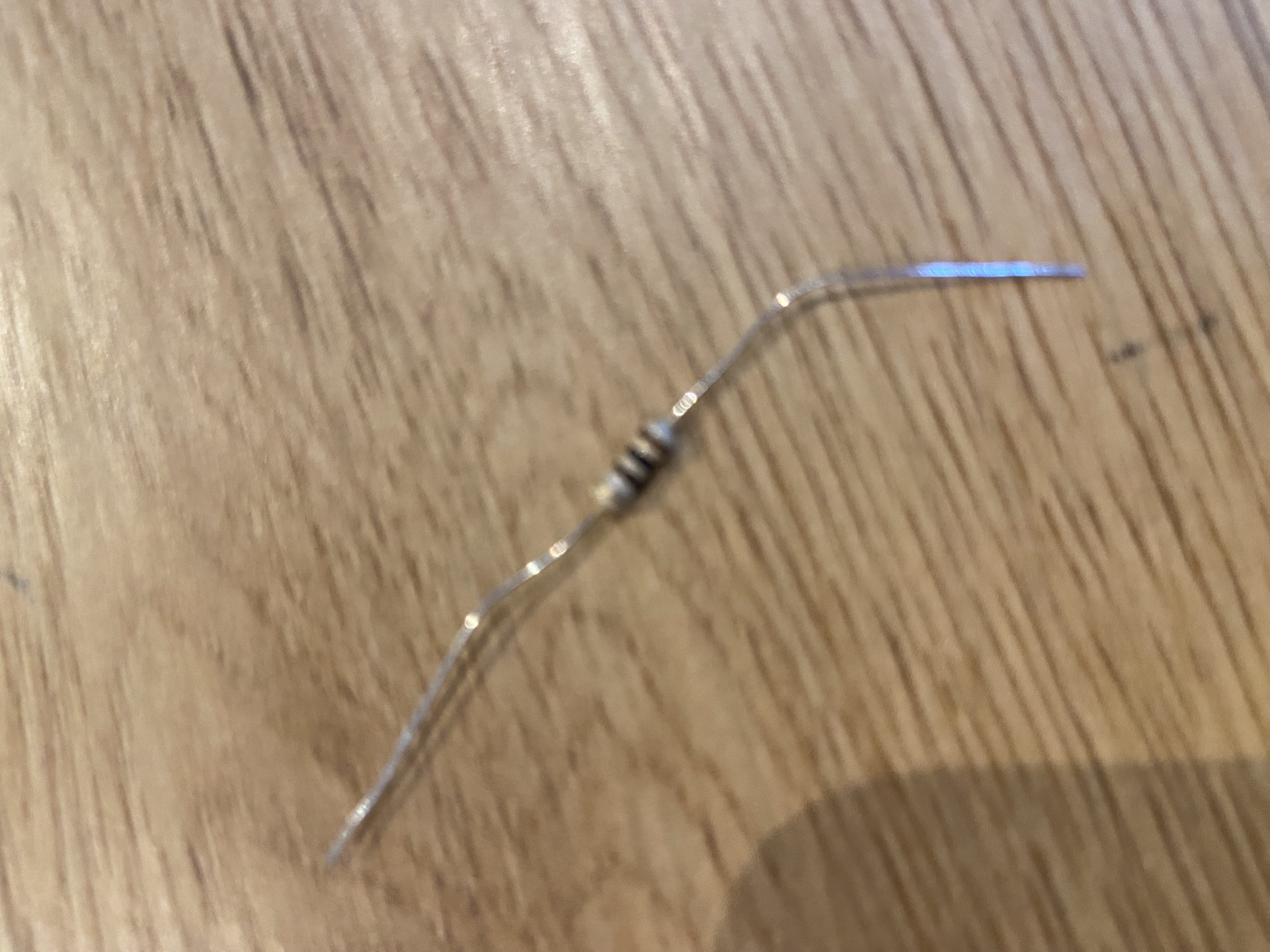
One 110 Ohm resistor
One lamp stand

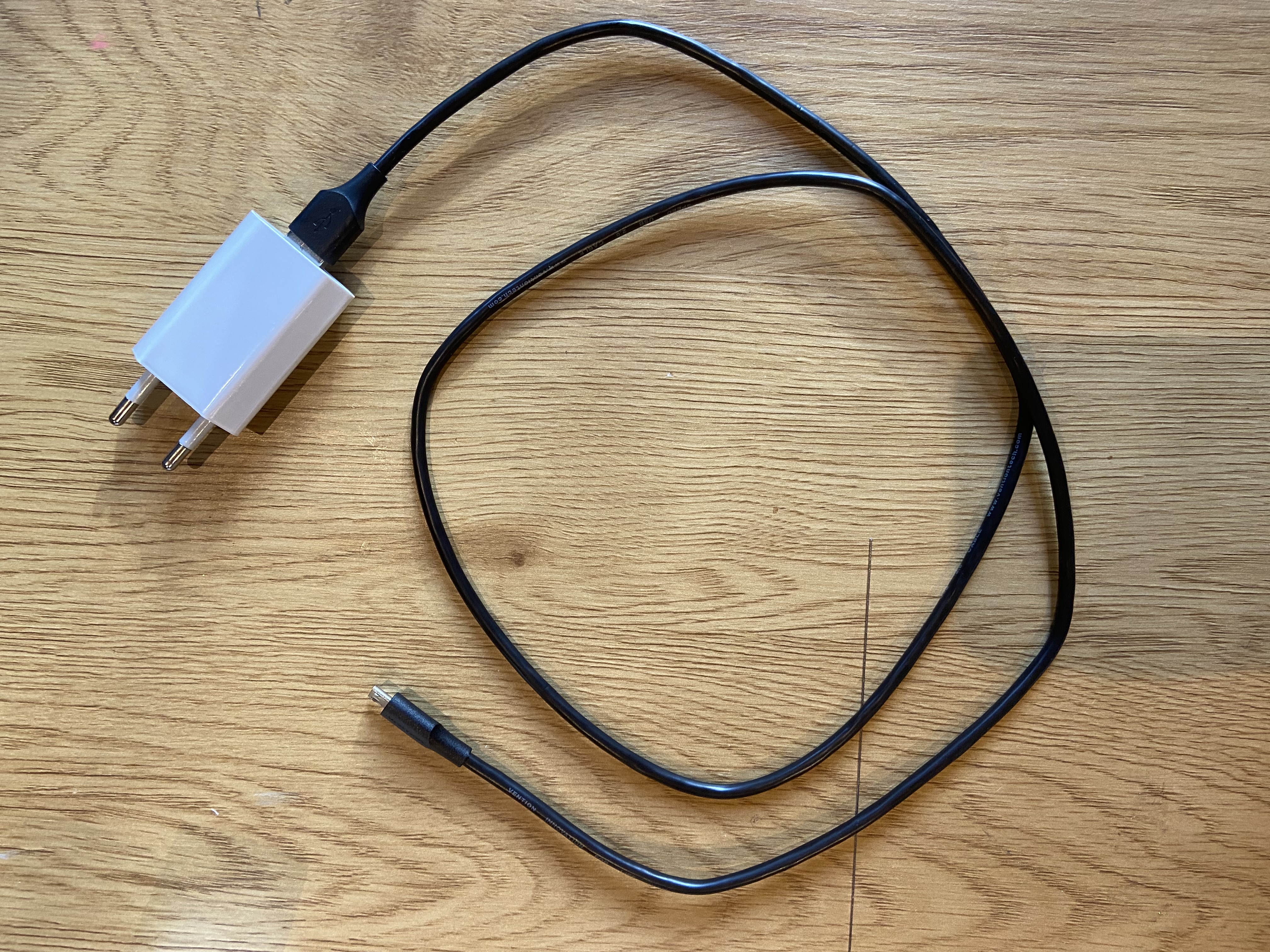
A USB cable and power adapter
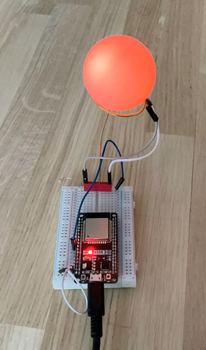
Assembling the device
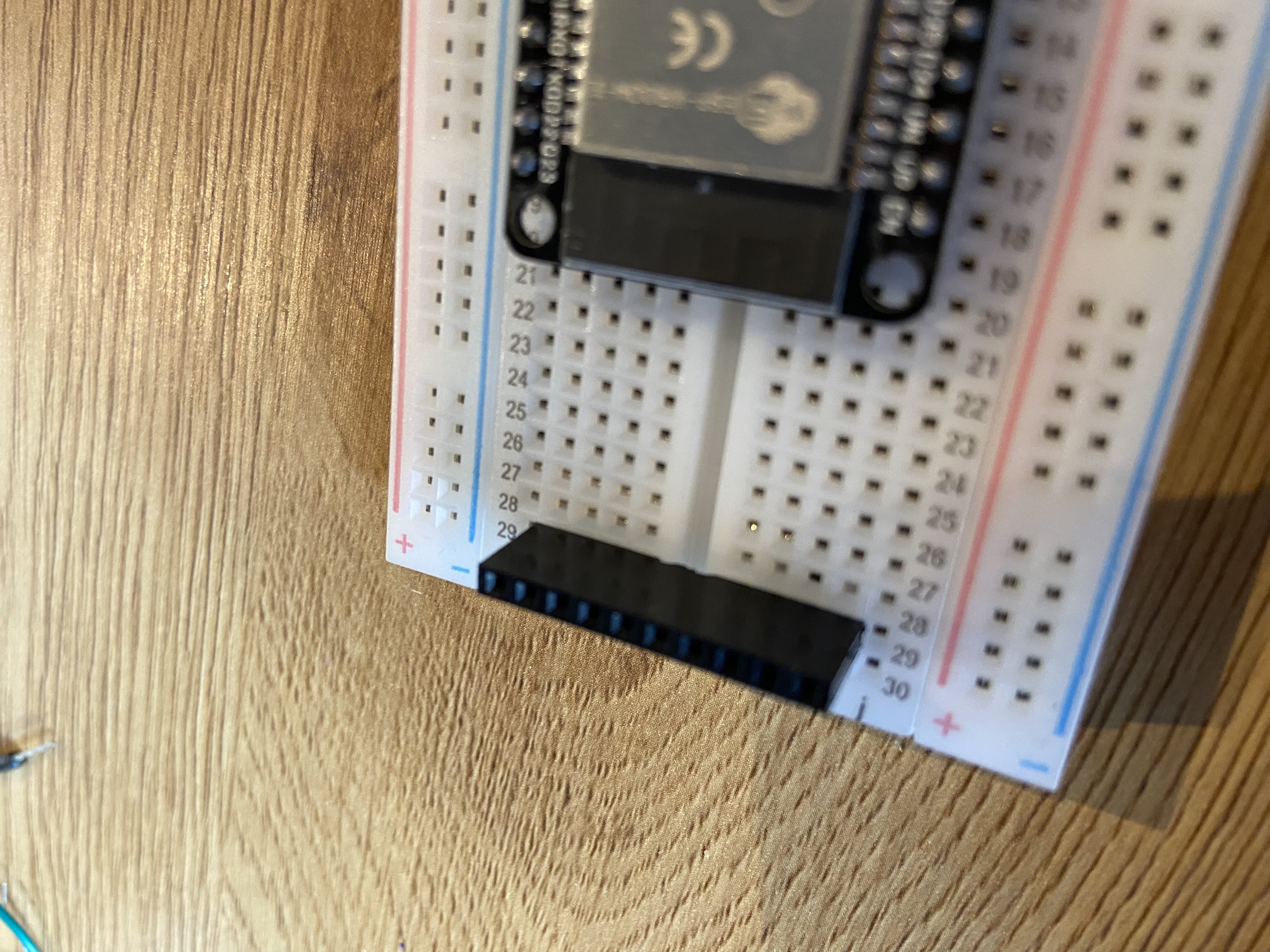
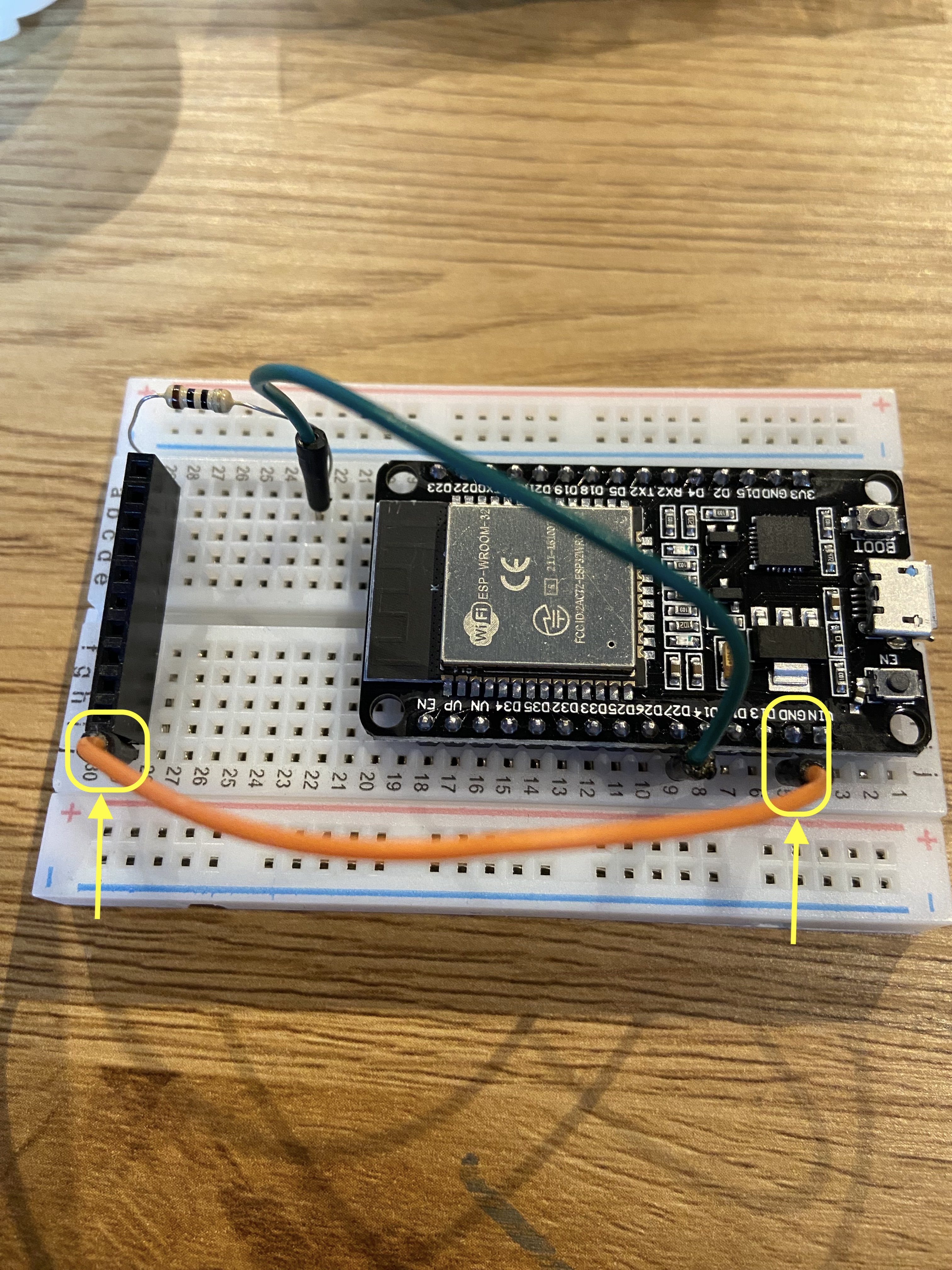
Insert the ESP32 development board onto the breadboard.
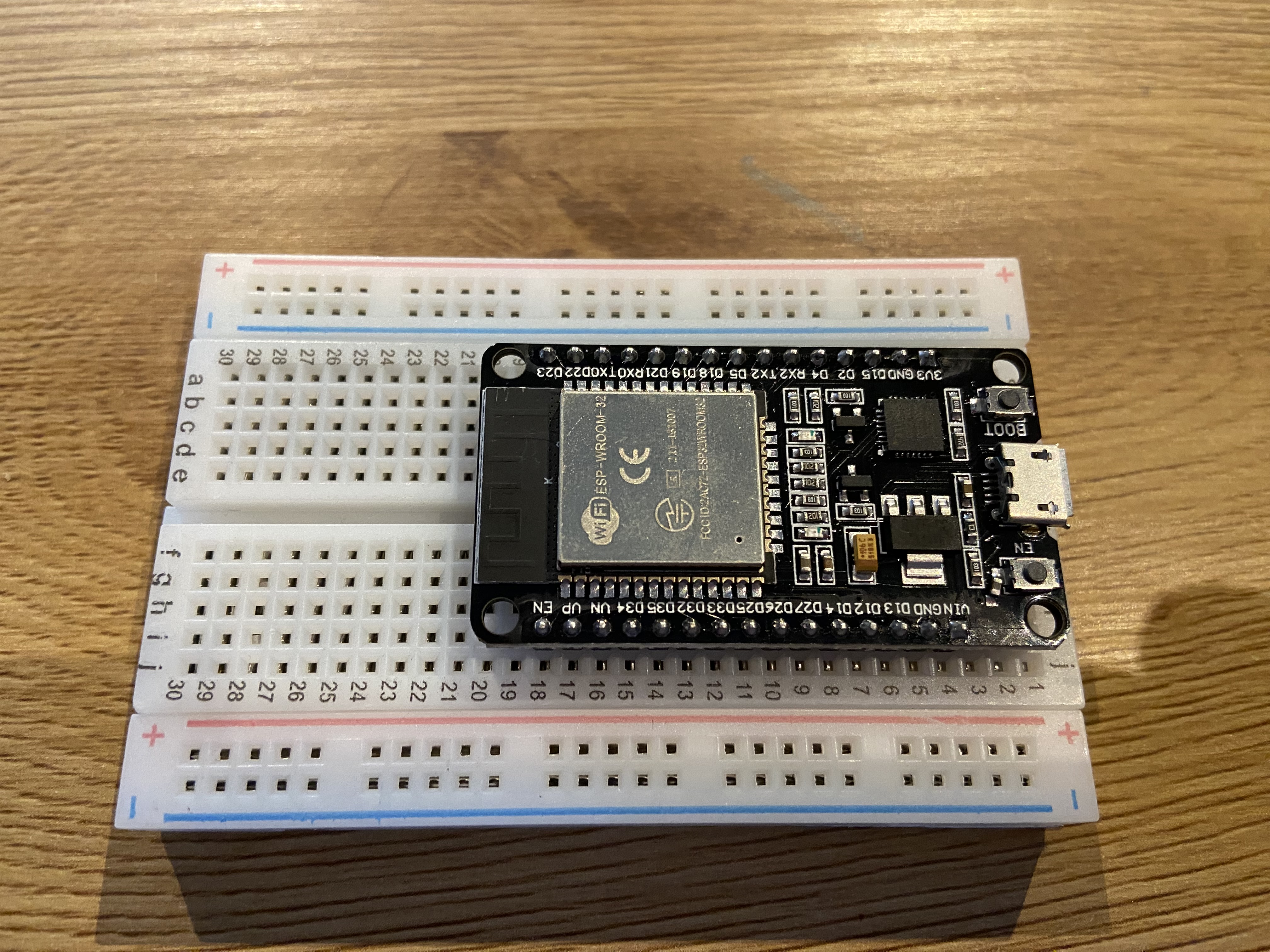
Mount the wire holder with LED onto the breadboard, leaving one breadboard slot on both sides
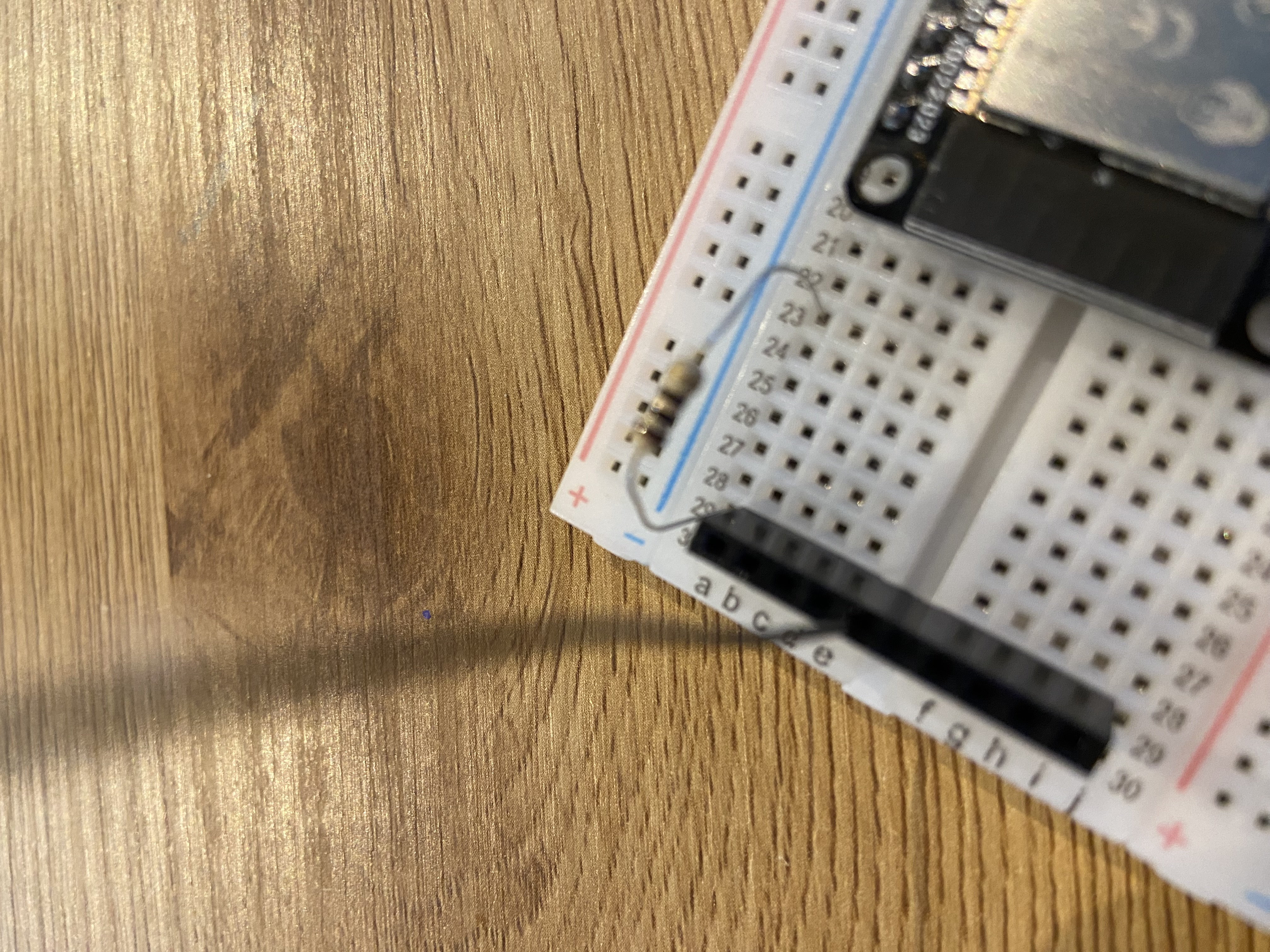
Place the resistor into a free space on the breadboard, and connect it to the free space above or below the LED holder.
Locate pin 27 on the ESP32 development board. Connect a wire from pin 27 of the ESP32 to one of the free slot in the same breadboard column as the resistor.
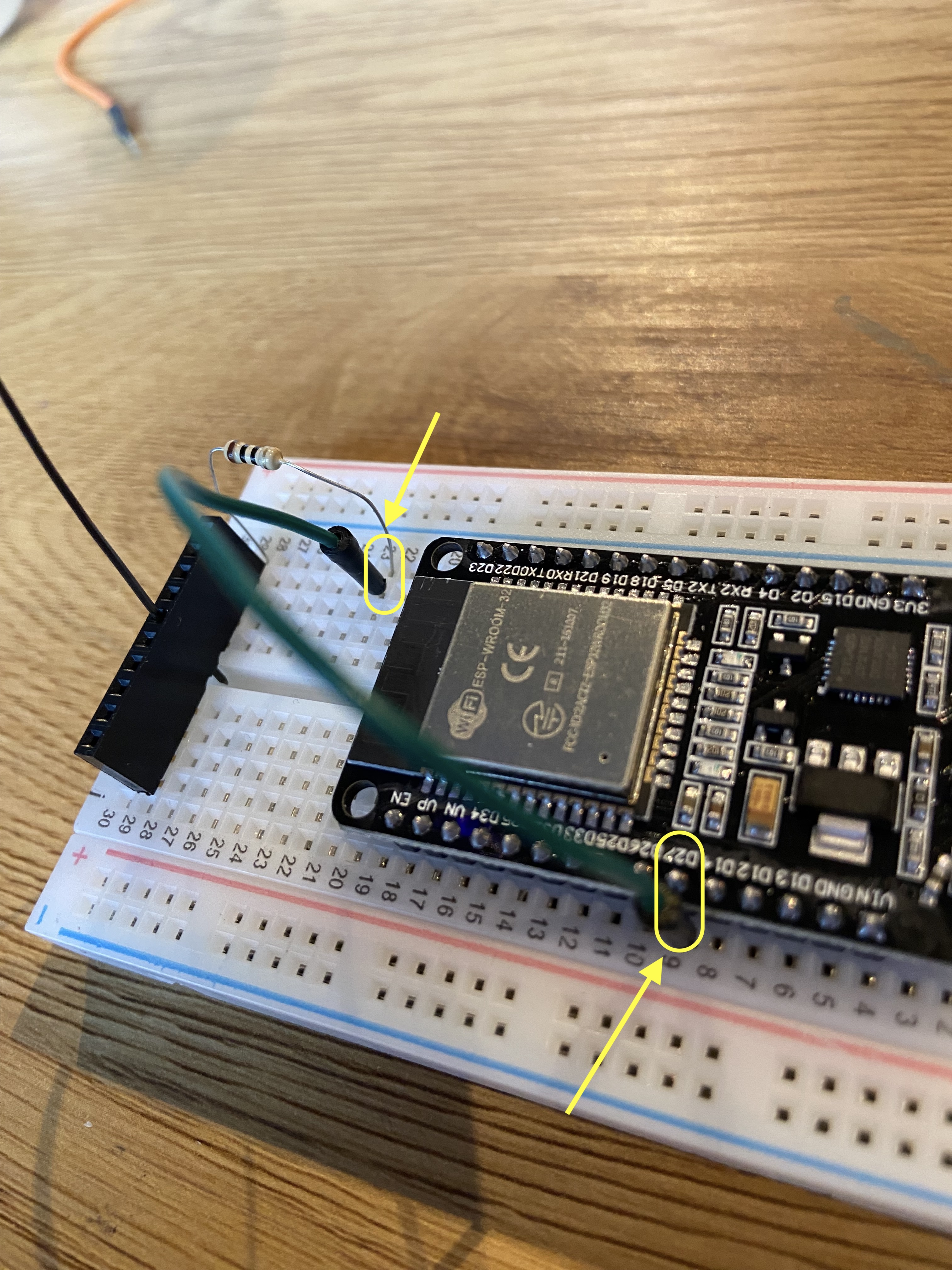
Connect a wire from a GND pin of the ESP32 to the other free slot below the LED holder.
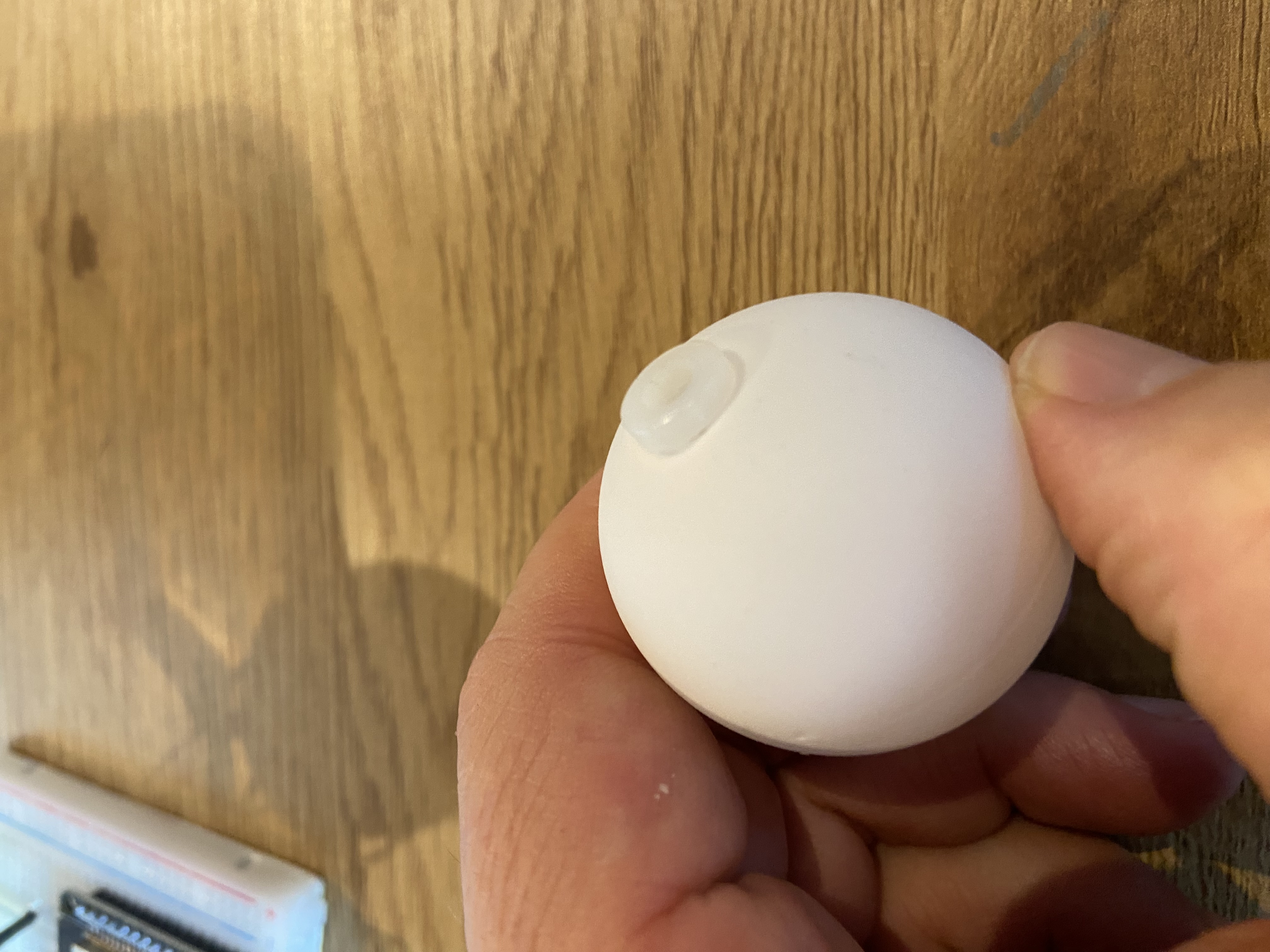
Take the table tennis ball and make a small hole large enough to mount the LED holder. (Some versions have the hole already prepared.)
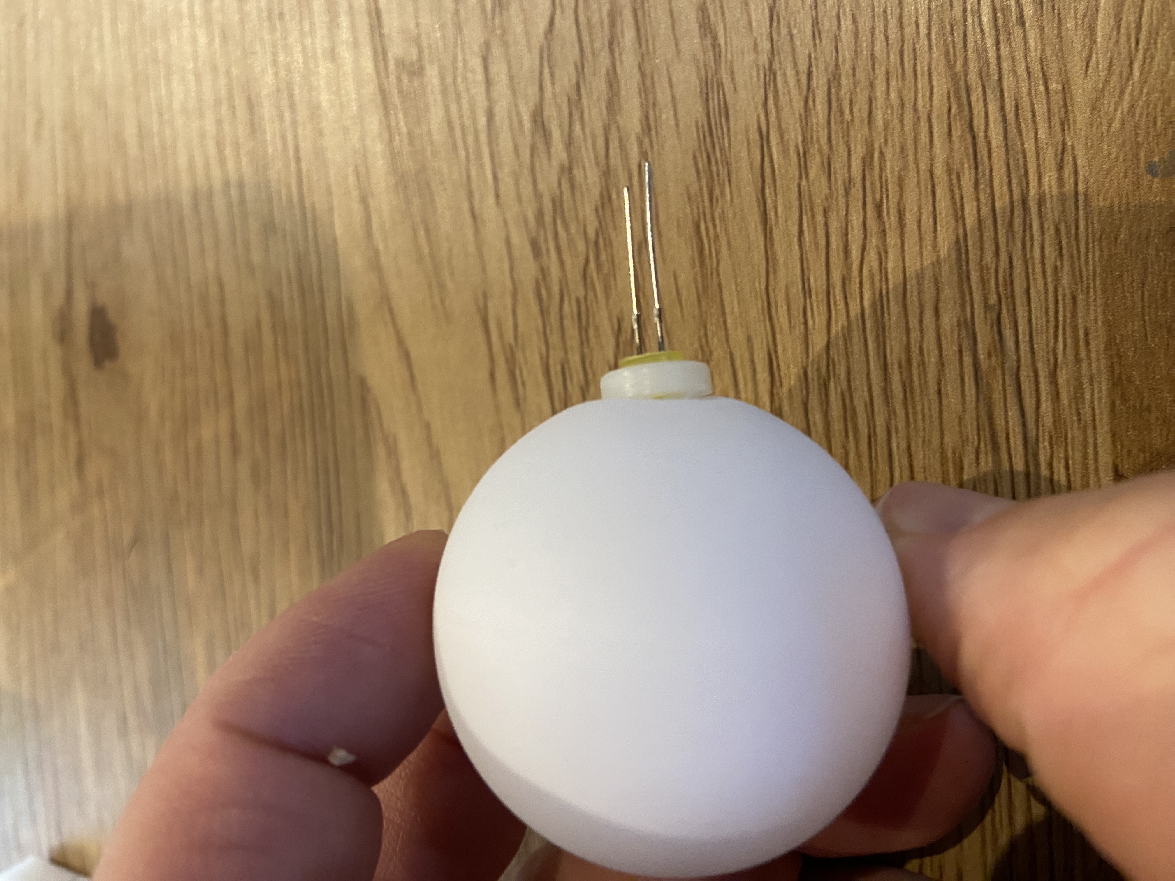
Insert the LED into the LED holder. Note that the LED legs have different lengths. Then place the holder into the hole in the tennis ball.
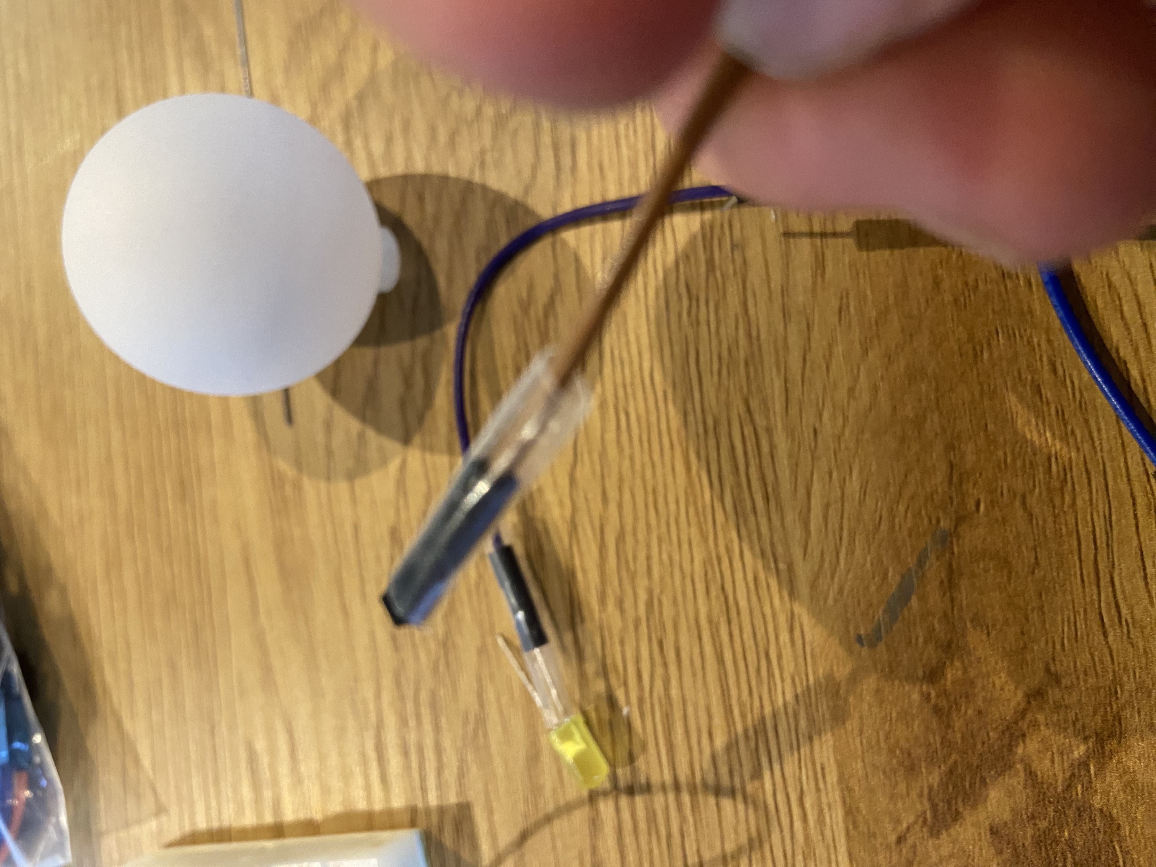
Insert the isolation tube over the wires that have a female plug.
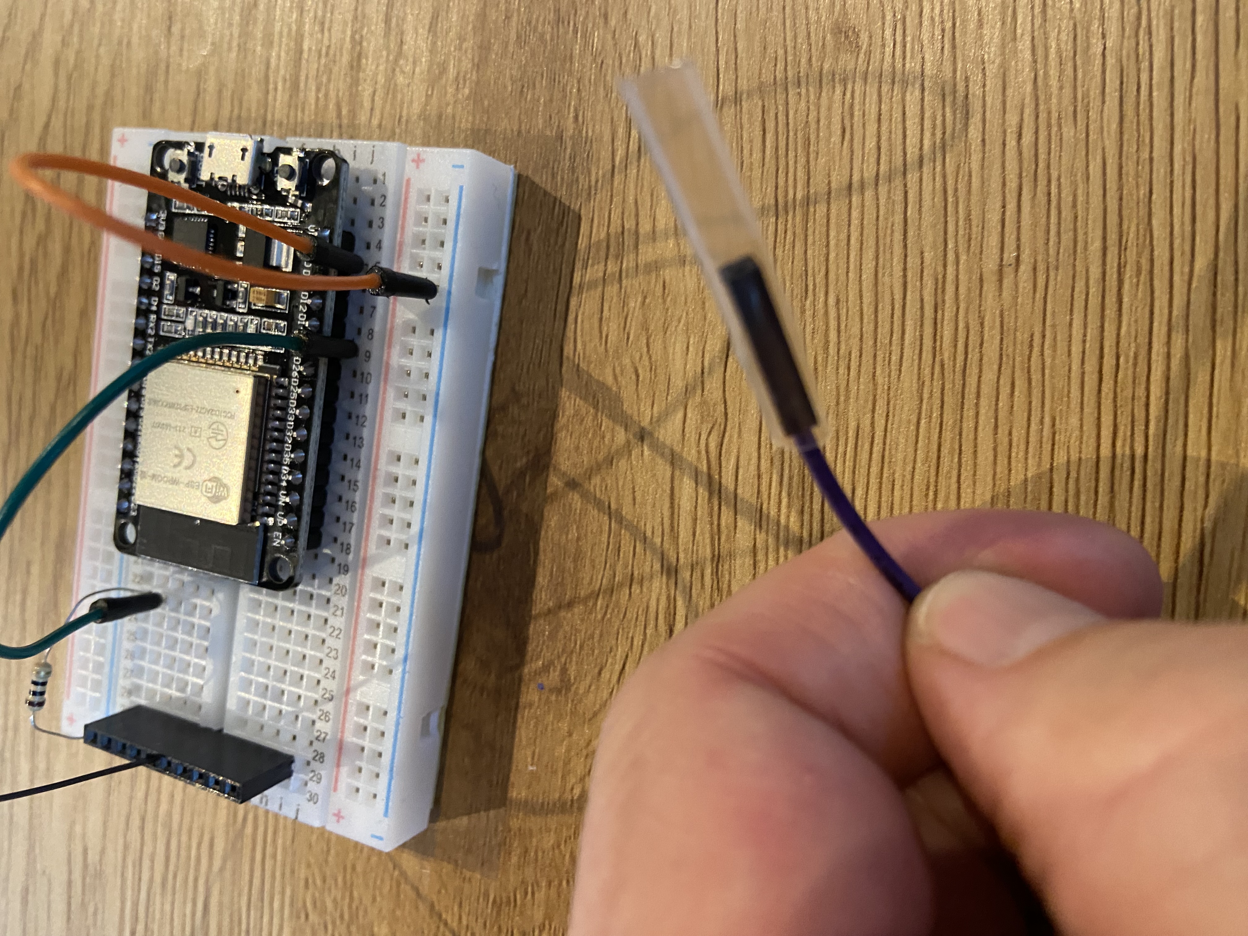
Connect a wire to each leg of the LED. Remember the color of the cables that connects to the short leg LED.
Assemble the wire holder, attaching one LED wire to each side. Ensure that the long leg of the LED (anode) is connected to the resistor side, and the short leg (cathode) goes to ground.
Insert the USB cable into the board, and plug it in. The LED should blink.
Your solar flare alert is now physically assembled and ready to connect to the WiFi.
Note: the isolation tubes can be settled by warming them. They will reduce their size.
Connecting to the WiFi
Power on the Solar Flare Alert. After a few seconds, the LED will begin blinking.
If the blinking stops after a few seconds, the device has successfully connected to a previously saved WiFi network.
If the LED continues blinking, open the WiFi settings on your phone or computer and connect to the access point named SolarFlareAlert-Setup.
Once connected, open a web browser and navigate to:
http://192.168.4.1Select your home WiFi network from the list and enter the password.
The device will reboot and attempt to join your network. When the LED turns solid green, the connection was successful.
You’re done. Reconnect your phone or computer to your normal WiFi. The Solar Flare Alert will now display the Sun’s current activity level.